3.8 Other point-based forces
All ArtiSynth components which are capable of exerting forces, including the axial springs of Section 3.1 and the frame springs of Section 3.7, are subclasses of ForceComponent. Other force effector types include PointPlaneForce and PointMeshForce, described in this section.
3.8.1 Forces between points and planes or meshes
A PointPlaneForce component produces forces between a point
and a plane, based on the point’s signed distance ![]() from the plane.
Similarly, a PointMeshForce component produces forces
between one or more points and a closed polygonal mesh, based on the signed
distance
from the plane.
Similarly, a PointMeshForce component produces forces
between one or more points and a closed polygonal mesh, based on the signed
distance ![]() to the mesh. These components thus implement “soft” constraint
forces that bind points to either a plane or a mesh. If the component’s unilateral property is set to true, as described below, forces are
applied only when
to the mesh. These components thus implement “soft” constraint
forces that bind points to either a plane or a mesh. If the component’s unilateral property is set to true, as described below, forces are
applied only when ![]() . This allows the simulation of force-based contact
between points and planes or meshes.
. This allows the simulation of force-based contact
between points and planes or meshes.
PointPlaneForce and PointMeshForce can be used for particles, FEM nodes and point-based markers, all of which are subclasses of Point.
These force components result in a force ![]() acting on the point given by
acting on the point given by
where ![]() is the signed distance to the plane (or mesh),
is the signed distance to the plane (or mesh), ![]() is the plane
normal (or surface normal at the nearest mesh point),
is the plane
normal (or surface normal at the nearest mesh point), ![]() is a stiffness
force and
is a stiffness
force and ![]() is a damping constant. The stiffness force may be either linear
or quadratic, according to
is a damping constant. The stiffness force may be either linear
or quadratic, according to
 |
where ![]() is a stiffness constant and the choice of linear or quadratic is
controlled by the component’s forceType property.
is a stiffness constant and the choice of linear or quadratic is
controlled by the component’s forceType property.
If the component’s unilateral property is set to true, then the
computed force will be 0 whenever ![]() :
:
 |
This allows plane and mesh force objects to implement “soft” collisions.
In the unilateral case, a quadratic force function provides smoother force transitions at
.
PointPlaneForce may be created with the following constructors:
| PointPlaneForce (Point p, Plane plane) |
Plane force component for point p |
| PointPlaneForce (Point p, Vector3d nrml, Point3d center) |
Plane is specified by its normal and center. |
Each of these creates a force component for a single point p, with the plane specified by either a Plane object or by its normal and center.
PointMeshForce may be created with the following constructors:
| PointMeshForce (MeshComponent mcomp) |
Mesh force for the mesh component mcomp. |
| PointMeshForce (String name, MeshComponent mcomp) |
Named mesh force for mesh mcomp. |
| PointMeshForce (String name, MeshComponent mcomp, Mdouble K, double D) |
Named mesh force with specified stiffness and damping. |
These create PointMeshForce for a mesh contained within a MeshComponent (Section 3.3). The mesh must a polygonal mesh composed of triangles.
The points associated with a PointMeshForce are added to after creation. The following methods are used to manage the point set:
| void addPoint (Point p) |
Adds point p. |
| boolean removePoint (Point p) |
Removes point p. |
| int numPoints() |
Returns the number of points. |
| Point getPoint (int idx) |
Returns the idx-th point. |
| void clearAllPoints() |
Removes all points. |
PointPlaneForce and PointMeshForce export a variety of properties that control their force behavior and appearance:
-
•
stiffness: A double value giving the stiffness constant
 .
Default value 1.0.
 -
•
damping: A double value giving the damping constant
 .
Default value 0.0.
 -
•
forceType: A value of type PointPlaneForce.ForceType or PointMeshForce.ForceType which describes the stiffness force, with the options being LINEAR and QUADRATIC. Default value LINEAR.
-
•
unilateral: A boolean value, which if true means that no force will be generated for
 . Default value false for
PointPlaneForce and true for PointMeshForce.
 -
•
enabled: A boolean value, which if false disables the component so that it will generate no force. Default value true.
-
•
planeSize: For PointPlaneForce only, a double value that gives the size of the plane for rendering purposes only. Default value 1.0.
The forces acting on each point can also be rendered in the viewer by setting the following additional properties:
-
•
drawForces: A boolean value, which if true causes the force on each point to be rendered using a line segment drawn from the point in the direction of the force. The length of each line segment is given by the force magnitude times the value of the forceLenScale property. Other render properties are controlled by the component’s generic line rendering properties.
-
•
forceLenScale: A double value, which if drawForces is true, is multiplied by the magnitude of each point force to determine the length of the rendered line segment.
These properties can be set either interactively in the GUI, or in code using their accessor methods.
3.8.2 Example: point plane forces

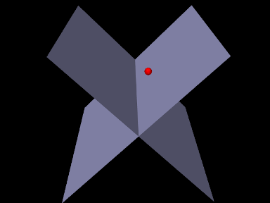
An example using PointPlaneForce is given by
artisynth.demos.tutorial.PointPlaneForces
which implements soft collision between a particle and two planes. The build() method is shown below:
A MechModel is created in the usual way (lines 2-3), followed by a
particle (lines 6-7). Then two PointPlaneForces are created to act on
this particle (lines 10-24), each centered on the origin, with plane normals of
![]() and
and ![]() , respectively. The forces are unilateral and
linear (the default), with a stiffness of 1000. Each plane’s size is set to 5;
this is for rendering purposes only, as the planes have infinite extent for
purposes of force calculation. Lastly, rendering properties are set (lines
27-28) to make the particle appear as a red sphere and the planes blue-gray.
, respectively. The forces are unilateral and
linear (the default), with a stiffness of 1000. Each plane’s size is set to 5;
this is for rendering purposes only, as the planes have infinite extent for
purposes of force calculation. Lastly, rendering properties are set (lines
27-28) to make the particle appear as a red sphere and the planes blue-gray.
To run this example in ArtiSynth, select All demos > tutorial > PointPlaneForces from the Models menu. When run, the particle will drop and bounce off the planes (Figure 3.35), finally coming to rest along the line where they intersect.
This model does not include damping, and so damping effects are due entirely to the default implicit integrator ConstrainedBackwardEuler. If the integrator is changed to an explicit one, using a directive such as
then the ball will continue to bounce during the simulation.
3.8.3 Example: point mesh forces

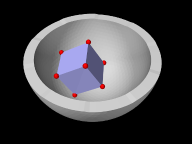
An example using PointMeshForce is given by
artisynth.demos.tutorial.PointMeshForces
which implements soft collision between a rigid cube and a bowl-shaped mesh, using a PointMeshForce to create force between the mesh and markers at the cube corners. The build() method is shown below:
A MechModel is created (lines 3-5), with inertialDamping set to 1.0 to help reduce oscillations as the cube bounces off the bowl. The cube itself is created as a RigidBody and positioned so as to fall into the bowl under gravity (lines 8-12). A frame marker is placed at each of the cube’s corners, using the (local) positions of its surface mesh vertices to determine the marker locations (lines 13-18); these markers will act as the collision points.
The bowl is constructed as a FixedMeshBody containing a mesh
read from the folder "data/" located beneath the source folder of the
model (lines 8-12). A PointMeshForce is then allocated for the bowl
(lines 28-34), with unilateral behavior (the default) and a quadratic stiffness
force with ![]() and
and ![]() . Each marker point is added to it to
enforce the collision. Lastly, rendering properties are set (lines 38-40) to
set the colors for the cube and bowl and make the markers appear as a red
spheres.
. Each marker point is added to it to
enforce the collision. Lastly, rendering properties are set (lines 38-40) to
set the colors for the cube and bowl and make the markers appear as a red
spheres.
To run this example in ArtiSynth, select All demos > tutorial > PointMeshForces from the Models menu. When run, the cube will drop into the bowl and bounce around (Figure 3.36).
Because of the discrete nature of the simulation, force-based collision handling is subject to the same time step limitations as constraint-based collisions (Section 8.9). In particular, insufficiently small time steps, or too small a stiffness, may cause objects to pass through each other. Insufficient damping may also result in excessive bouncing.