11.1 Implementation
This section describes the technical details of the ArtiSynth skinning
mechanism. A skin mesh is implemented using a
SkinMeshBody, which contains a
base mesh and references to a set of underlying dynamic master
bodies. A master body can be either a
Frame (of which
RigidBody is a subclass), or a
FemModel3d. The positions of the
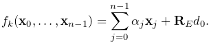
mesh vertices (along with markers and other points that can be
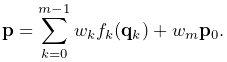
attached to the skin mesh) are determined by a weighted sum of
influences from each of the ![]() master bodies, such that as the latter
move and/or deform, the vertices and attached points deform as
well. More precisely, for each master body
master bodies, such that as the latter
move and/or deform, the vertices and attached points deform as
well. More precisely, for each master body
![]() , let
, let ![]() be the weighting factor and
be the weighting factor and
![]() the connection function that describes the
contribution of body
the connection function that describes the
contribution of body ![]() to the position of the vertices (or attached
points) as a function of its generalized coordinates
to the position of the vertices (or attached
points) as a function of its generalized coordinates ![]() . Then if
the position of a vertex (or attached point) is denoted by
. Then if
the position of a vertex (or attached point) is denoted by ![]() and
its initial (or base) position is
and
its initial (or base) position is ![]() , we have
, we have
 |
(11.1) |
The weight ![]() in the last term is known as the base weight
and describes an optional contribution from the base position
in the last term is known as the base weight
and describes an optional contribution from the base position ![]() .
Usually
.
Usually ![]() , unless the vertex is not connected to any
master bodies, in which case
, unless the vertex is not connected to any
master bodies, in which case ![]() , so that the vertex is anchored
to its initial position.
, so that the vertex is anchored
to its initial position.
In general, connection weights ![]() are computed based on the
distances
are computed based on the
distances ![]() between the vertex (or attached point) and
each master body
between the vertex (or attached point) and
each master body ![]() . More details on this are given in Sections
11.2 and 11.3.
. More details on this are given in Sections
11.2 and 11.3.
For Frame master bodies, the connection function is one associated with various rigid body skinning techniques known in the literature. These include linear, linear dual quaternion, and iterative dual quaternion skinning. Which technique is used is determined by the frameBlending property of the SkinMeshBody, which can be queried or set in code using the methods
where FrameBlending is an enumerated type defined by SkinMeshBody with the following values:
- LINEAR
-
Linear blending, in which the connection function
 implements a
standard rigid connection between the vertex and the frame
coordinates. Let the frame’s generalized coordinates
implements a
standard rigid connection between the vertex and the frame
coordinates. Let the frame’s generalized coordinates  be given
by the
be given
by the  rotation matrix
  and translation vector
  describing its pose, with its initial pose given by
  and
and
 . The connection function then takes the form
(11.2) Linear blending is faster than other blending techniques but is more prone to pinching and creasing artifacts in the presence of large rotations between frames.
- DUAL_QUATERNION_LINEAR
-
Linear dual quaternion blending, which is more computationally expensive but typically gives better results than linear blending, and is described in detail as DLB in [8]. Let the frame’s generalized coordinates
be given by the dual-quaternion
 (describing both rotation and translation), with the
initial pose given by the dual-quaternion
(describing both rotation and translation), with the
initial pose given by the dual-quaternion  . Then define
the relative dual-quaternion
. Then define
the relative dual-quaternion  as
as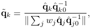
(11.3) where the denominator is formed by summing over all master bodies
 which are frames. The connection function is then
given by
which are frames. The connection function is then
given by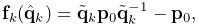
(11.4) where we note that a dual quaternion multiplied by a position vector yields a position vector.
- DUAL_QUATERNION_ITERATIVE
-
Dual quaternion iterative blending, which is a more complex dual quaternion technique described in detail as DIB in [8]. The connection function for iterative dual quaternion blending involves an iterative process and is not described here. It also does not conform to (11.1), because the connection functions
for the Frame master
bodies do not combine linearly. Instead, if there
are  Frame master bodies, there is a single
connection function
Frame master bodies, there is a single
connection function
(11.5) that determines the connection for all of them, given their weighting factors
 and generalized coordinates
  .
Iterative blending relies on two parameters: a blend tolerance, and a
maximum number of blend steps, both of which are controlled by the
SkinMeshBody properties DQBlendTolerance and DQMaxBlendSteps, which have default values of
.
Iterative blending relies on two parameters: a blend tolerance, and a
maximum number of blend steps, both of which are controlled by the
SkinMeshBody properties DQBlendTolerance and DQMaxBlendSteps, which have default values of  and
and  .
.Iterative dual quaternion blending is not completely supported in ArtiSynth. In particular, because of its complexity, the associated force and velocity mappings are computed using the simpler computations employed for linear dual quaternion blending. For the examples shown in this chapter, iterative dual quaternion gives results that are quite close to those of linear dual quaternion blending.
For FEM master bodies, the connection works by tying each vertex (or
attached point) to a specific FEM element using a fixed-length offset
vector ![]() that rotates in conjunction with the element. This is
illustrated in Figure 11.2 for the case of a
single FEM master body. Starting with the initial vertex position
that rotates in conjunction with the element. This is
illustrated in Figure 11.2 for the case of a
single FEM master body. Starting with the initial vertex position
![]() , we find the nearest point
, we find the nearest point ![]() on the nearest FEM
element, along with the offset vector
on the nearest FEM
element, along with the offset vector ![]() . The point
. The point ![]() can be expressed as the weighted
sum of the initial element nodal positions
can be expressed as the weighted
sum of the initial element nodal positions ![]() ,
,
 |
(11.6) |
where ![]() is the number of nodes and
is the number of nodes and ![]() represent the
(constant) nodal coordinates. As the element moves and deforms, the
element point
represent the
(constant) nodal coordinates. As the element moves and deforms, the
element point ![]() moves with the nodal positions
moves with the nodal positions ![]() according
to the same relationship, while the offset vector
according
to the same relationship, while the offset vector ![]() rotates
according to
rotates
according to ![]() , where
, where ![]() is the rotation of the
element’s coordinate frame
is the rotation of the
element’s coordinate frame ![]() with respect to its initial
orientation. The connection function
with respect to its initial
orientation. The connection function ![]() then takes the form
then takes the form
 |
(11.7) |
![]() is determined by computing a polar decomposition
is determined by computing a polar decomposition ![]() on the deformation gradient
on the deformation gradient ![]() at the element’s center. We note that
the displacement
at the element’s center. We note that
the displacement ![]() is only rotated and so the distance
is only rotated and so the distance ![]() of the vertex from the element remains constant. If the
vertex is initially on or inside the element, then
of the vertex from the element remains constant. If the
vertex is initially on or inside the element, then ![]() and
(11.7) takes the form of a standard point/element
attachment as described in 6.4.3.
and
(11.7) takes the form of a standard point/element
attachment as described in 6.4.3.

While it is sometimes possible to determine weights
that control a vertex position outside an element, without the need for an offset vector
, the resulting vertex positions tend to be very sensitive to element distortions, particularly when the vertex is located at some distance. Keeping the element-vertex distance constant via an offset vector usually results in more plausible skinning behavior.
![[LOGO]](data:image/png;base64,iVBORw0KGgoAAAANSUhEUgAAAAsAAAAOCAYAAAD5YeaVAAAAAXNSR0IArs4c6QAAAAZiS0dEAP8A/wD/oL2nkwAAAAlwSFlzAAALEwAACxMBAJqcGAAAAAd0SU1FB9wKExQZLWTEaOUAAAAddEVYdENvbW1lbnQAQ3JlYXRlZCB3aXRoIFRoZSBHSU1Q72QlbgAAAdpJREFUKM9tkL+L2nAARz9fPZNCKFapUn8kyI0e4iRHSR1Kb8ng0lJw6FYHFwv2LwhOpcWxTjeUunYqOmqd6hEoRDhtDWdA8ApRYsSUCDHNt5ul13vz4w0vWCgUnnEc975arX6ORqN3VqtVZbfbTQC4uEHANM3jSqXymFI6yWazP2KxWAXAL9zCUa1Wy2tXVxheKA9YNoR8Pt+aTqe4FVVVvz05O6MBhqUIBGk8Hn8HAOVy+T+XLJfLS4ZhTiRJgqIoVBRFIoric47jPnmeB1mW/9rr9ZpSSn3Lsmir1fJZlqWlUonKsvwWwD8ymc/nXwVBeLjf7xEKhdBut9Hr9WgmkyGEkJwsy5eHG5vN5g0AKIoCAEgkEkin0wQAfN9/cXPdheu6P33fBwB4ngcAcByHJpPJl+fn54mD3Gg0NrquXxeLRQAAwzAYj8cwTZPwPH9/sVg8PXweDAauqqr2cDjEer1GJBLBZDJBs9mE4zjwfZ85lAGg2+06hmGgXq+j3+/DsixYlgVN03a9Xu8jgCNCyIegIAgx13Vfd7vdu+FweG8YRkjXdWy329+dTgeSJD3ieZ7RNO0VAXAPwDEAO5VKndi2fWrb9jWl9Esul6PZbDY9Go1OZ7PZ9z/lyuD3OozU2wAAAABJRU5ErkJggg==)